MIL-DTL-62270B(AT)
3.4.1.21.2 Smoke grenade discharger circuits.
3.4.1.21.2.1 Arming. The power-on (ready) lamp in the grenade power box shall
illuminate when the master battery switch and the grenade system power switch are both on
(see 4.7.1.22.1.1).
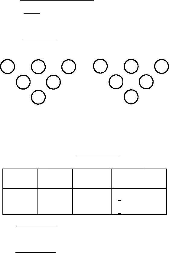
3.4.1.21.2.2 Circuit voltage. Voltage at the smoke grenade discharger firing pins shown
in figure 1 shall be as indicated in table I when the power-on firing push-button is actuated
(see 4.7.1.22.1.2).
3
2
1
1
2
3
4
5
5
4
6
6
RIGHT SIDE
LEFT SIDE
DISCHARGER
DISCHARGER
(13-12-34)
(13-12-35)
VIEW FROM DRIVER'S POSITION
FIGURE 1. Firing pin positions.
TABLE I. Smoke grenade discharger firing pin voltage.
Left side
Right side
Firing
discharger
discharger
push-button
firing pins
firing pins
Voltage
Right
1, 2, 5
3, 4, 6
Vehicle (Ref. 3.2.1.3)
Right
3, 4, 6
1, 2, 5
0 + 0.5 Vdc
Left
3, 4, 6
1, 2, 5
Vehicle (Ref. 3.2.1.3)
Left
1, 2, 5
3, 4, 6
0 + 0.5 Vdc
3.4.1.22 In-tank fuel pumps. Each pump shall be capable of producing a minimum
pressure of 5 pounds per square inch gage (psig) at the engine end of the fuel line disconnect
under no-flow conditions (see 4.7.1.23).
3.4.1.23 Fuel return system. The fuel return selector valve shall divert fuel to the tanks as
indicated by the pointer on top of the valve (see 4.7.1.24).
9
For Parts Inquires submit RFQ to Parts Hangar, Inc.
© Copyright 2015 Integrated Publishing, Inc.
A Service Disabled Veteran Owned Small Business